Separate ordinary tip wear from a damaged tool
Gradual loss of working-tip material can be part of service wear, but the acceptable condition depends on the tool and application. A crack, fracture, substantial deformation or damaged retention area is a different concern and should not be treated as a routine sharpening decision.
Stop if the tool or its retention is compromised. Preserve the removed tool and its identity for assessment. A fracture surface can lose useful evidence if it is ground, hammered or otherwise modified before the cause has been reviewed.
Use the damage location to ask better questions
Damage near the working end may need assessment of contact conditions and the selected tip profile. Damage at the guided shank or retaining area also calls attention to guide condition, geometry and abnormal loading. Deformation at the striking end raises a different set of questions about contact, alignment and material condition.
Appearance is not proof. A fracture can involve fatigue, overload, a material issue or a combination, and a technician may need dimensional or material examination to distinguish them. Do not label every broken tool as too hard or every deformed end as too soft from a photograph alone.
| Finding | Associated inspection scope |
|---|---|
| Uneven shank wear | Tool straightness, guide condition and alignment |
| Damage at a retaining groove | Tool reference, groove geometry and retainers |
| Deformed striking end | Mating impact surfaces and contact condition |
| Cracked or fractured section | Preserved fracture, load history and qualified assessment |
| Unusual tip wear | Material, selected profile and working method |
Inspect the components that guide and retain it
The tool works within a system of bushings, retainers and the impact interface. Excessive or uneven guide wear can change the load path. A damaged retaining component or incorrect groove geometry can also create a problem that a new tip profile will not solve.
Check the specified lubrication and operating history, including any prying or repeated loss of contact. Review these as possible contributors rather than automatic grounds for rejecting a material claim or warranty request. The technical finding should connect the observed damage with the evidence available.
For example, a broken tool replaced with the same nominal diameter may fail again if the original guided length or retaining groove was incorrect for the breaker. Conversely, an accurately matched replacement will not correct a guide system already outside its acceptance criteria. Keep the tool identity and the guide inspection in the same case. This prevents a material discussion from overlooking an interface problem that can be established directly from the assembly requirements.
Define the new tool by its complete interface
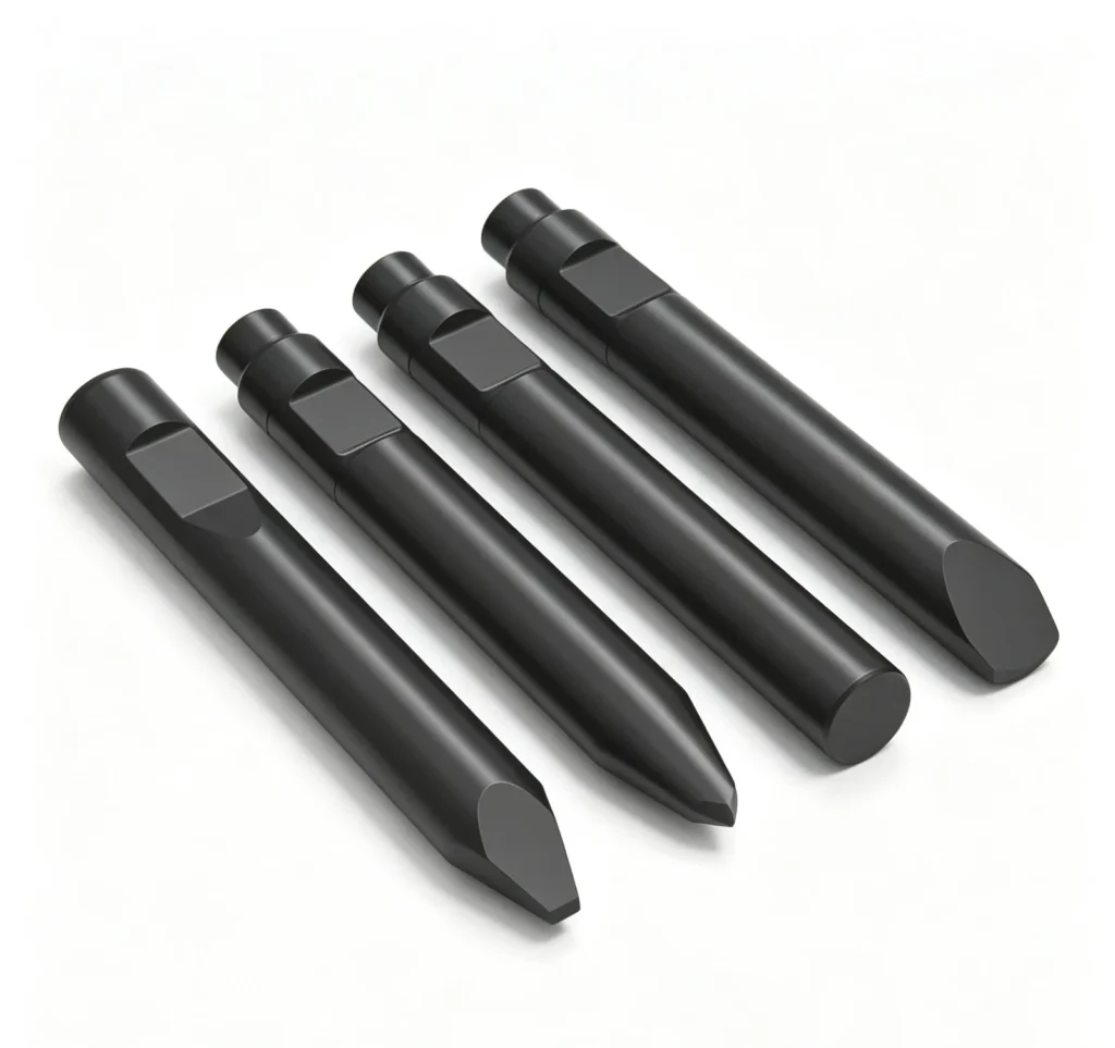
Order the correct shank, retaining features, striking-end geometry, overall configuration and tip profile. Match the drawing and revision rather than assuming that tools with the same nominal diameter are interchangeable. Any material or inspection requirement should be agreed separately and clearly.
For NEWLAND supply, a defined replacement can be reviewed alongside bushings, pins or other confirmed affected parts. Reconditioning should only be considered where the approved limits and method permit it. A welded or heavily ground tool should not be returned to impact service on the basis that its outside shape appears restored.