
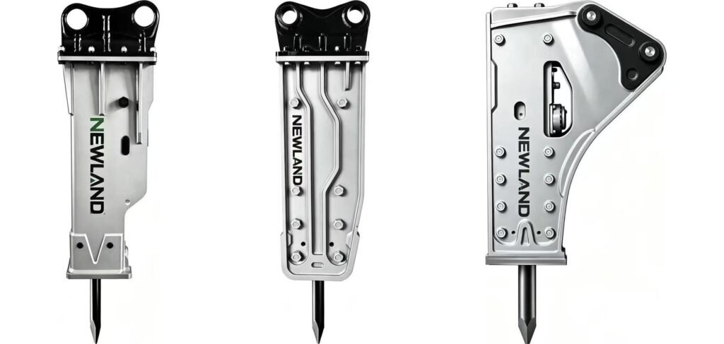
Define which interface the dimensions describe
Hydraulic breaker mounting dimensions are useful only when the measured interface is identified. A carrier pin connection, the two sides of a coupler and a breaker bracket can all appear in the same assembly. Their measurements should remain separate until a complete connection drawing shows how they relate.
Begin by naming the components and drawing the proposed chain of connection. Mark existing items, new items and any adapter. This gives every photograph and measurement a clear destination in the assembly instead of creating a collection of numbers without reference points.
Use a labeled dimension record
State the units on the drawing, even when every measurement uses the same unit. If a part is worn, describe the condition and distinguish an observed dimension from an approved nominal dimension. A worn surface may not represent the original design.
| Dimension or detail | How to make the record unambiguous |
|---|---|
| Pin diameter | Identify the pin position and mating component |
| Pin center distance | Show which two axes define the distance |
| Bracket internal width | Identify the reference faces and measurement location |
| Offsets and overall envelope | Show the relationship to the connection axes |
| Retaining and locking details | Identify the approved arrangement and relevant drawing reference |
Photographs explain orientation; drawings control the order
Take an overall image to show the connection and closer views to show relevant features. A visible scale helps explain size, but photographs alone can hide offsets, widths and reference faces. A measured or approved drawing is the stronger basis for ordering a mounting component.
Do not estimate a critical dimension from perspective or convert an uncertain measurement into a precise drawing. Mark uncertain items for confirmation. If access requires supporting, disconnecting or moving the attachment, the measurement work belongs within the appropriate safe procedure and should be performed by competent personnel.
Check the assembled envelope
A bracket can connect while the complete assembly still needs a clearance review. Include the breaker body, hoses, coupler and adapters when considering the intended range of movement. The drawing should make the combination clear enough for the carrier and attachment review to use the same geometry.
For example, a hypothetical adapter may preserve the pin sizes but change the breaker position. That does not prove the adapter is unsuitable, but it does mean the original clearance assumption needs review. Matching connection dimensions and approving the installed envelope are related but separate decisions.
Keep changes under one revision reference
If a bracket width, offset or coupler changes, issue a revised drawing and identify which earlier version it replaces. A final quotation should refer to the approved revision. Avoid accepting a message that says “make it like the photo” while the attached drawing still describes an older configuration.
NEWLAND supplies mounting brackets and adapters within its breaker-parts range. Use the quick coupler article for the coupler’s specific interface questions and the general compatibility checklist for the complete carrier review. The mounting drawing should provide a reproducible mechanical specification, while hydraulic suitability is checked through the separate circuit record.
Related products and guides
Hydraulic Breaker Compatibility Checklist: Carrier, Oil Circuit and Mounting
Quick Coupler Compatibility: A Measurement Checklist Before You Order
Hydraulic Breaker Mounting Brackets and Adapters
Using a Hydraulic Breaker with a Quick Coupler: What to Confirm Before Ordering
How to Choose a Hydraulic Breaker
Hydraulic Breaker for a Backhoe: Matching Before You Order
Hydraulic Breaker Matching for Special Carrier Setups